SAE Meaning
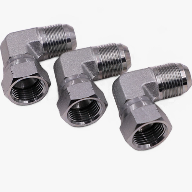
SAE (Society of Automotive Engineers) hydraulic fittings are hydraulic system connections, including couplings, flanges, hoses, fittings, etc., designed to SAE standards. These fittings are based on standardized interface sizes, pressure ratings and material specifications to ensure global hydraulic system versatility and compatibility.

SAE Size Chart
SAE J512
| Inch size | Dash size | Thread Size | Male Thread O.D. (in) | Female thread O.D (in) | ||
| 1⁄8 | -2 | 5⁄16 – 24 | 5⁄16 | 0.31 | 9⁄32 | 0.27 |
| 3⁄16 | -3 | 3⁄8 – 24 | 3⁄8 | 0.38 | 11⁄32 | 0.34 |
| 1⁄4 | -4 | 7⁄16 – 20 | 7⁄16 | 0.44 | 13⁄32 | 0.39 |
| 5⁄16 | -5 | 1⁄2 – 20 | 1⁄2 | 0.50 | 15⁄32 | 0.45 |
| 3⁄8 | -6 | 5⁄8 – 18 | 5⁄8 | 0.63 | 9⁄16 | 0.57 |
| 1⁄2 | -8 | 3⁄4 – 16 | 3⁄4 | 0.75 | 11⁄16 | 0.69 |
| 5⁄8 | -10 | 7⁄8 – 14 | 7⁄8 | 0.88 | 13⁄16 | 0.81 |
| 3⁄4 | -12 | 1 1⁄16 – 14 | 11⁄16 | 1.06 | 1 | 0.99 |
| 7⁄8 | -14 | 1 1⁄4 – 12 | 1 1⁄4 | 1.25 | 1 5⁄32 | 1.16 |
| 1 | -16 | 1 3⁄8 – 12 | 1 3⁄8 | 1.38 | 1 9⁄32 | 1.29 |
SAE Straight Thread O-ring (O-Ring Boss) SAE J1926-1 and ISO 11296-1
| Inch size | Dash size | Thread Size | Male Thread O.D. (in) | Female thread O.D (in) | ||
| 1⁄8 | -2 | 5⁄16 – 24 | 5⁄16 | 0.31 | 9⁄32 | 0.27 |
| 3⁄16 | -3 | 3⁄8 – 24 | 3⁄8 | 0.38 | 11⁄32 | 0.34 |
| 1⁄4 | -4 | 7⁄16 – 20 | 7⁄16 | 0.44 | 13⁄32 | 0.39 |
| 5⁄16 | -5 | 1⁄2 – 20 | 1⁄2 | 0.50 | 15⁄32 | 0.45 |
| 3⁄8 | -6 | 9⁄16 – 18 | 9⁄16 | 0.56 | 17⁄32 | 0.51 |
| 1⁄2 | -8 | 3⁄4 – 16 | 3⁄4 | 0.75 | 11⁄16 | 0.69 |
| 5⁄8 | -10 | 7⁄8 – 14 | 7⁄8 | 0.88 | 13⁄16 | 0.81 |
| 3⁄4 | -12 | 1 1⁄16 – 12 | 1 1⁄16 | 1.06 | 1 | 0.98 |
| 7⁄8 | -14 | 1 3⁄16 – 12 | 1 3⁄16 | 1.19 | 1 1⁄8 | 1.10 |
| 1 | -16 | 1 5⁄16 – 12 | 1 5⁄16 | 1.31 | 1 1⁄4 | 1.23 |
| 1 1⁄4 | -20 | 1 5⁄8 – 12 | 1 5⁄8 | 1.63 | 1 9⁄16 | 1.54 |
| 1 1⁄2 | -24 | 1 7⁄8 – 12 | 1 7⁄8 | 1.88 | 1 13⁄16 | 1.79 |
| 2 | -32 | 2 1⁄2 – 12 | 2 1⁄2 | 2.50 | 2 7⁄16 | 2.42 |
Main Applications of SAE Fittings
Construction Machinery: High-pressure oil line connections for excavators and cranes.
Agricultural machinery: Tractor hydraulic suspension system piping.
Industrial equipment: power transmission for injection molding machines and hydraulic machine tools.
Aerospace: precision connections for landing gear hydraulic control systems.
SAE Fittings Technical Specifications and Core Parameters
SAE Fittings Pressure Rating
Low Pressure: SAE 3000 PSI (approx. 207 MPa) for hydraulic tank return lines.
High Pressure: SAE 6000 PSI (approx. 414 MPa) for excavator main pump outlet.
SAE Fittings Interface Standards
SAE J514: Straight Thread Fittings (O-ring seal).
SAE J518: Four-bolt flange (for high flow scenarios).
SAE J1453: Standard for rubber hose fittings.
SAE Fittings Material Selection
Carbon Steel: Economical solution, suitable for general hydraulic oil environment.
Stainless steel 316: corrosion resistant, used for acidic media in ships or chemical plants.
Brass: Low pressure gauge connection scenario.
SAE Fittings Temperature Range
Standard NBR seals are suitable for -40℃~+100℃.
Viton seals can withstand -20℃~+200℃ high temperature oil.
SAE Fittings Professional Installation Guide
SAE Fittings Pre-installation Inspection
Use a borescope to check the inner wall of the pipeline for machining burrs (>Ra 08μm requires rework).
Perform flatness inspection of SAE flanges, requiring <005mm/m.
SAE Fittings Sealing treatment
O-ring needs to be immersed in hydraulic oil for 30 minutes before installation, and the expansion rate is controlled at 5%-8%.
Tighten the bolts in three times in diagonal order when the flange is connected, and the final torque refers to SAE J518 standard table.
SAE Fittings Pressure test
Initial pressurization is done by step-up method: 25%→50%→75%→100% of the rated pressure, with each stage holding pressure for 5 minutes.
Use ultrasonic leak detector to detect micro leakage (sensitivity ≥ 01mL/min).
SAE Fittings Common Problems and Solutions
SAE Fittings Seal Failure (about 60% of failures)
1 Phenomenon
Oil seepage from joints, oil film buildup on flange faces (>3 drops/minute)
Seal brittleness during start-up at low temperatures (common below -20°C)
2 Underlying causes
Material aging: Nitrile rubber (NBR) at 100 ℃ above the continuous work led to an increase in hardness (Shaw’s hardness change > 15)
Improper installation: O-ring compression rate exceeds the standard range of 20% -30
Media compatibility: biodegradable hydraulic oil (HEES) dissolved fluorine rubber (FKM)
3 Solution
Change to Hydrogenated Nitrile Butadiene Rubber (HNBR) to increase temperature resistance to 150°C.
Use a seal gap gauge (e.g. Parker ORD 5700) to control compression.
Select EPDM rubber seals for environmentally friendly fluids.
SAE Fittings Threaded Connection Failure
1 Phenomenon
Fitting root fracture (common on SAE J514 37° flare fittings)
Slipping threads after repeated disassembly (UNF fine threads are susceptible)
2 Failure Mechanism
Vibration fatigue: the intrinsic frequency of the pipeline and the engine vibration spectrum overlap (200-300Hz danger zone)
Over-torque: exceeding the SAE J518 standard torque value by 20% leads to stress corrosion.
Galvanic coupling corrosion: stainless steel fittings and carbon steel piping contact to form a potential difference
3 Improvement Measures
Installation of damping bracket (damping coefficient>03)
Adopt torque+turning angle control method (final turning angle error <±5°) Use of insulating shims (resistance >1MΩ) to isolate foreign metals.
SAE Fittings Hydraulic Shock Damage
1 Typical failure
Deformation of four-bolt flange (flatness > 01mm/m)
Hose fitting pull-out (peak pulse pressure >15 times rated pressure)
2 Failure Analysis
Water hammer caused by reversing valve response time >30ms
Accumulator precharge pressure deviates ±10% from standard value
3 Suppression Program
Add pilot operated relief valve at pump outlet (response time <5ms)
Use SAE J517C couplings with pressure peak suppression.
Regularly check accumulator nitrogen pressure (monthly deviation control <5%)
SAE Fittings special working condition problems
1 Extreme cold environment (-40℃)
Phenomenon: The viscosity of hydraulic oil increases dramatically, resulting in a sudden rise in pressure.
Countermeasures: replace with low condensation hydraulic oil (pour point <-50 ℃) and install the oil preheating system
2 Marine salt spray corrosion
Phenomenon: 316 stainless steel joints pitting corrosion (Cl-concentration> 100ppm)
Protection: use of super duplex steel (UNS S32750) or surface spraying WC-Co coating
3 High-pressure water jet system (>100MPa)
Hazard: O-ring extrusion damage
Upgrade program: Step Seal construction with PTFE retaining ring.
Conclusion
By understanding the characteristics of SAE Fittings through this Ultimate Guide to SAE Fittings, engineers and purchasers can make more informed choices to ensure the reliability and safety of hydraulic systems. If you have further questions or suggestions about SAE Fittings, please feel free to consult with one of our hydraulic engineers and we will answer them at no cost to you.