Meaning of the JIC standard for connection fittings
JIC (Joint Industry Council) is a standard for hydraulic fittings developed in 1945 by the Society of Automotive Engineers (SAE) in conjunction with industry associations under SAE J514. Its core feature is the 37° taper seal (compatible with ISO 84342 ferrule fittings), which is used in a wide range of applications such as industrial hydraulics, construction machinery, agricultural equipment and aerospace. Aerospace.
JIC Connection Fittings Model and Size System
JIC fittings are designated by a “number + suffix” which represents 16 times the hose diameter in inches (i.e., “Dash Size”):
| Dash Size | Hose Passage (in.) | Thread Size (UN/UNF) | Common Metric Equivalents |
| 4 | 1/4″ | 7/16″20 UNF | M12×1.5 |
| 6 | 3/8″ | 9/16″18 UNF | M18×1.5 |
| 8 | 1/2″ | 3/4″16 UNF | M22×1.5 |
| 10 | 5/8″ | 7/8″14 UNF | M26×1.5 |
| 12 | 3/4″ | 11/16″12 UN | M30×2.0 |
Note: Suffix may indicate form (e.g., straight/elbow) or material (e.g., SS = stainless steel).
JIC Connection Fittings Size Chart
| Size Designation | Taper width, “A”, inches | Thread width, “B”, inches | Thread Spec. “C” | Shoulder width, “D” inches | Shoulder Diameter, “E”, inches | Fitting Length, “F”, inches | Bore Diameter, “H”, inches | Tip Diameter, “I”, inches |
|---|---|---|---|---|---|---|---|---|
| 2 | 0.111 | 0.208 | 5/16” – 24 UNF | 0.067 | 0.250 | 0.448 | 0.062 | 0.083 |
| 3 | 0.11 | 0.239 | 3/8” – 24 UNF | 0.067 | 0.312 | 0.479 | 0.125 | 0.146 |
| 4 | 0.114 | 0.282 | 7/16” – 20 UNF | 0.080 | 0.364 | 0.550 | 0.172 | 0.193 |
| 5 | 0.114 | 0.282 | 1/2” – 20 UNF | 0.080 | 0.426 | 0.550 | 0.234 | 0.255 |
| 6 | 0.108 | 0.275 | 9/16″ – 18 UNF | 0.090 | 0.481 | 0.556 | 0.281 | 0.318 |
| 7 | — | — | — | — | — | — | — | — |
| 8 | 0.155 | 0.310 | 3/4” – 16 UNF | 0.098 | 0.659 | 0.657 | 0.406 | 0.426 |
| 9 | — | — | — | — | — | — | — | — |
| 10 | 0.155 | 0.385 | 7/8” – 14 UNF | 0.111 | 0.772 | 0.758 | 0.531 | 0.539 |
| 11 | — | — | — | — | — | — | — | — |
| 12 | 0.185 | 0.424 | 1-1/16” – 12 UN | 0.130 | 0.943 | 0.943 | 0.609 | 0.664 |
| 13 | — | — | — | — | — | — | — | — |
| 14 | 0.186 | 0.450 | 1-3/16″ – 12 UN | 0.129 | 1.068 | 0.890 | 0.719 | 0.788 |
| 15 | — | — | — | — | — | — | — | — |
| 16 | 0.186 | 0.471 | 1-5/16″ – 12 UN | 0.129 | 1.193 | 0.911 | 0.844 | 0.913 |
| 17 | — | — | — | — | — | — | — | — |
| 18 | — | — | — | — | — | — | — | — |
| 19 | — | — | — | — | — | — | — | — |
| 20 | — | — | 1-5/8” – 12 UN | — | — | 0.96 | 1.078 | — |
Reference: https://en.wikipedia.org/wiki/JIC_fitting
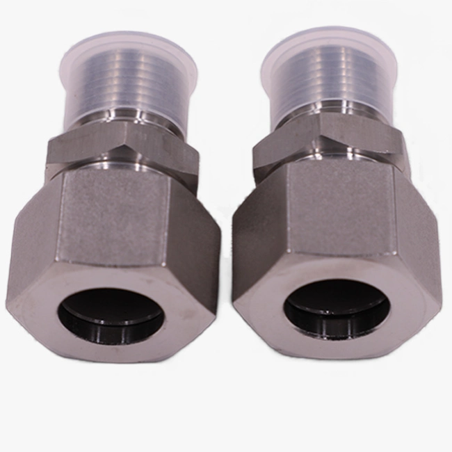
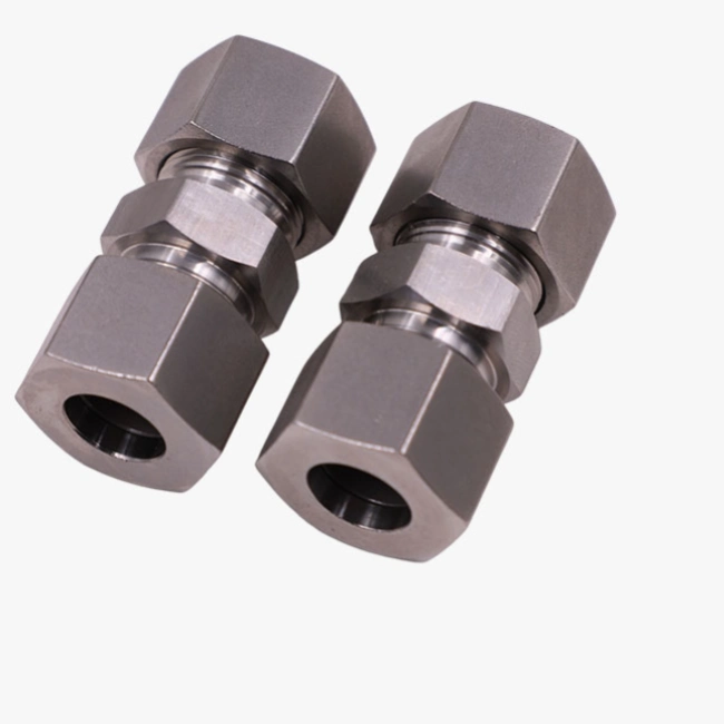
JIC Connection Fittings Core Structural Characteristics
JIC Connecting Fittings Sealing Angle:
37° metal taper (not 45° SAE flange or 30° AN aerial fitting), metal-to-metal sealing by taper extrusion.
JIC Connecting Fittings Material:
Carbon steel: zinc-plated/phosphated surface, economical and universal (suitable for mineral oils).
Stainless steel (304/316): corrosion resistant, food/marine environment
Brass: low pressure, corrosion-resistant occasions
JIC Connection Fittings Pressure Rating
| Dash Size | Maximum Working Pressure (psi) |
| 4 ~ 8 | 5,000 ~ 6,000 psi |
| 10 ~ 16 | 3,000 ~ 4,000 psi |
Note: Actual pressures are affected by system design, vibration, and temperature; a safety margin is required.
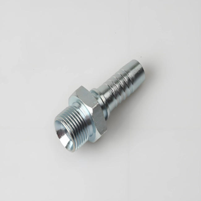
How to Identify JIC Connection Fittings
Visual inspection:
37° tapered sealing face (as distinguished from SAE 45° or NPT threaded seals)
UN/UNF straight thread (not tapered for NPT)
Marking Identification:
Fitting bodies are often marked with “JIC” or Dash Size (e.g. “8”)
Thread size stamping (e.g. “3/416”)
JIC Connection Fittings Installation Torque Guide
Excessive tightening will result in taper deformation leakage! Reference Values (Dry Mount, Carbon Steel)
| Dash Size | Recommended torque (N-m) | Recommended torque (ftlb |
| 6 | 25~30 | 18~22 |
| 8 | 40~50 | 30~37 |
| 10 | 60~75 | 44~55 |
Key Tips:
Clean the sealing surface and prohibit the use of sealant!
Stainless steel fittings require 20% more torque (low coefficient of friction)
JIC connection fittings sealing principle
Metal-to-metal wire contact sealing:
When the nut is tightened, it pushes the 37° inner taper and 37° outer taper to extrude, generating plastic deformation at the contact line and forming a high-pressure sealing band.
Advantages: high temperature resistance, impact resistance, long life.
Disadvantages: sensitive to scratches, requires precise machining.
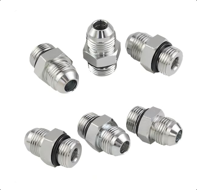
Adaptation options for different forms of JIC connection fittings
Adaptation to other standards:
JIC to NPT: tapered threads require sealant (not an ideal solution)
JIC to SAE: 45 ° plane sealing need to add O-ring (SAE straight thread)
JIC to BSPP: G thread through the transition connector to match
System extension form:
JIC flange: high flow line connection
JIC quick-change couplings: quick release with self-sealing valve
JIC to ORFS: High sealing flat sealing solution
Related reading:
jic fitting vs an fitting buying decision guide
Common Problems and Solutions in Different Situations of JIC Connection Accessories
| Problems | Possible Causes | Solutions |
| Oil seepage at fittings | Scratched/contaminated taper | Replace fittings, clean system |
| Leakage even after tightening | Deformation due to insufficient torque/over-tightening | Reinstallation with standard torque |
| Thread galling | Cold weld stainless steel threads | Use anti-seize, do not overtorque |
| Vibration causing loosening | Not using anti-loosening glue/lock nut | Apply thread adhesive, change to lock nut |
| Leakage at peak pressure | Poor machining of taper angle | Replacement of high-precision couplings |
JIC Connection Accessories Selection and Maintenance Recommendations
System compatibility: ensure that the sealing surface angle is the same (do not mix 37 ° and 45 °)
Corrosive environment: prefer 316 stainless steel
Periodic Inspection: Check torque every 500 hours in a vibrating environment.
Leak Response: Use JIC Seal Repair Kits (temporary filling of taper scratches).
SAFETY WARNING: Relieve pressure from hydraulic system before operating! Incorrect installation may result in injury from high pressure oil injection.
Conclusion:
With their reliable metal seals and standardized design, JIC connection fittings have become the universal language of hydraulic systems worldwide. A proper understanding of their technical details is the key to guaranteeing leak-free system operation.
For model specific torque tables or dimensional drawings, provide them to our technical engineers who will answer your queries free of charge.